Chapter 3: Scenarios & Selection
Eight real-world deployment scenarios with photorealistic illustrations, technical specifications, and selection guidance.
Selecting the appropriate segmentation model requires a clear understanding of the deployment environment, the sensitivity of data being protected, the operational constraints of the team, and the compliance requirements that must be satisfied. This chapter presents eight canonical deployment scenarios, each with a photorealistic illustration, a description of the environment and key design decisions, and a table of primary technical indicators. These scenarios are not mutually exclusive — many real-world deployments combine elements from two or more scenarios.
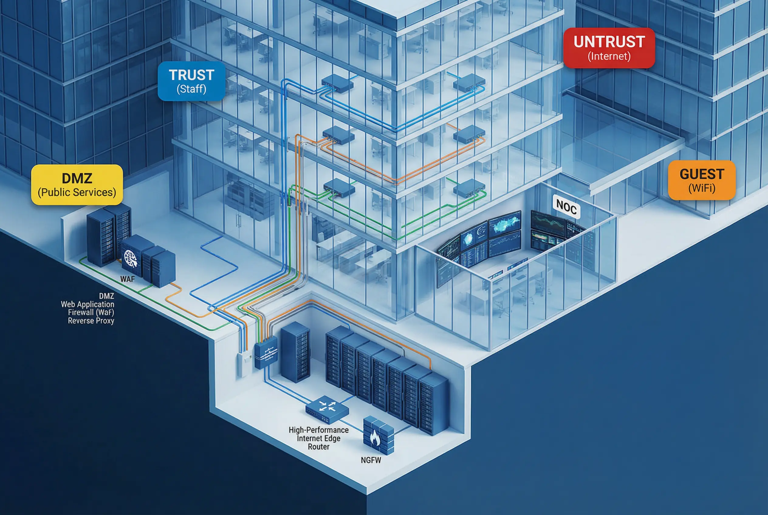
Figure 3.1: Enterprise Campus Network — Multi-story office building with color-coded VLAN conduits, edge NGFW, DMZ rack, and NOC visible through glass walls.
The enterprise campus scenario is the most common starting point for segmentation projects. The network serves a mixed population of managed endpoints, guest devices, printers, IoT devices, and production-adjacent systems. The primary risk is a compromised endpoint in the Office zone pivoting to production systems or sensitive data stores. The design uses 802.1X-enforced VLANs at the access layer, with an ISFW or NGFW enforcing inter-VLAN routing policies at the distribution/core layer. Guest and IoT VLANs are strictly isolated with no path to internal systems.

Figure 3.2: Data Center Three-Tier Architecture — Leaf-spine topology with labeled App, Data, Management, and Security tiers, ISFW appliances between tiers, and SIEM monitoring station.
The data center scenario requires east–west micro-segmentation in addition to north–south boundary controls. The leaf-spine fabric provides high-bandwidth, low-latency connectivity between workloads, while the segmentation layer enforces that App tier servers can only reach Data tier via specific service accounts and ports, and that Management tier access is restricted to the bastion host. Distributed firewall policies (host-based or hypervisor-based) supplement physical ISFW appliances for workload-level granularity. The Security tier receives log streams from all other tiers and has read-only visibility into all zones.
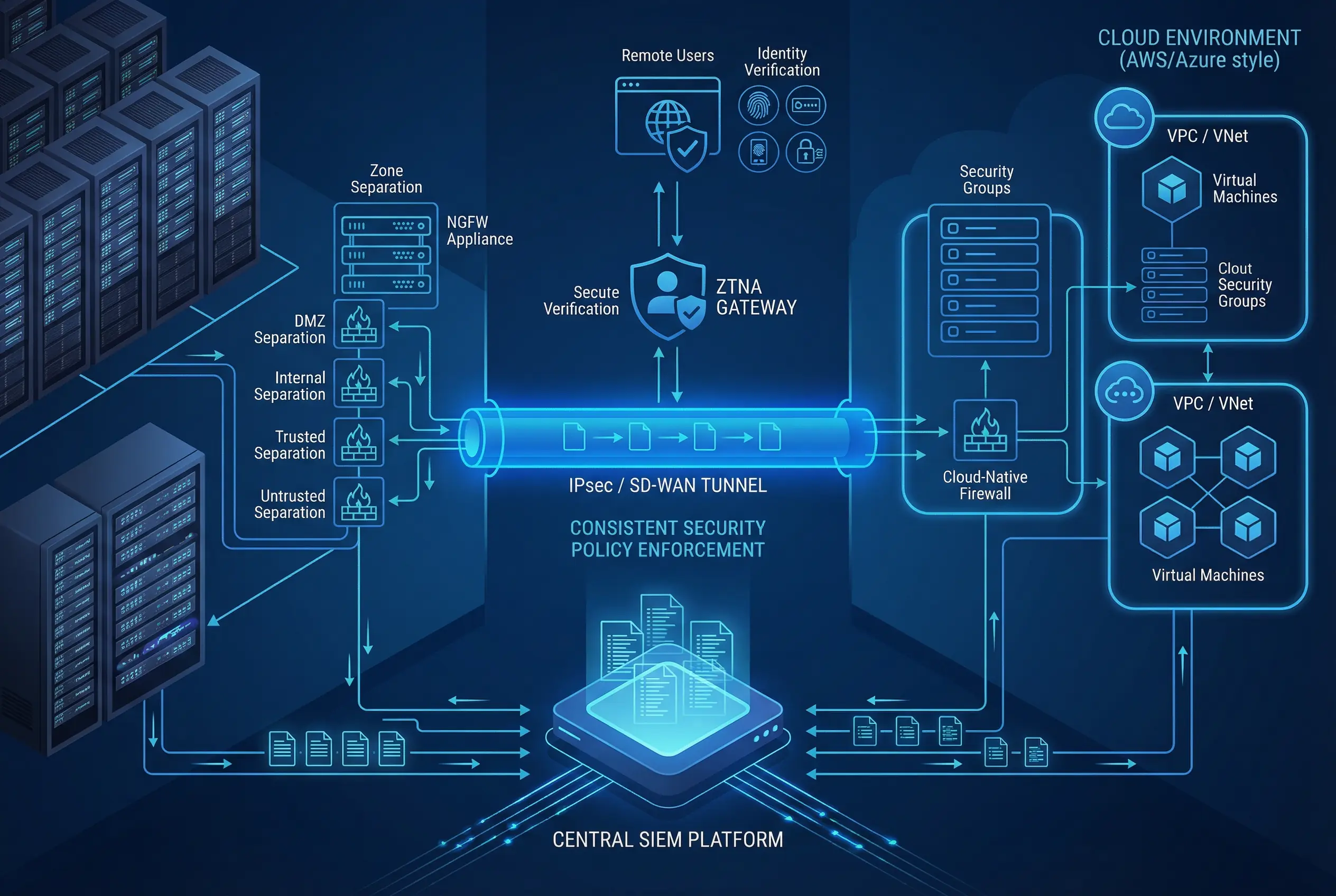
Figure 3.3: Hybrid Cloud Architecture — Split-screen showing on-premises NGFW zones connected via IPsec/SD-WAN tunnel to cloud VPC security groups, with ZTNA gateway for remote users and central SIEM at bottom.
The hybrid cloud scenario presents the challenge of maintaining consistent segmentation policy across environments where IP addresses are ephemeral and security group membership changes dynamically. The design uses a combination of IPsec or SD-WAN encrypted tunnels for site-to-site connectivity, cloud-native security groups for east–west control within each cloud environment, and a ZTNA gateway as the single entry point for remote users. Policy-as-code tools ensure that the same logical segmentation intent is enforced regardless of whether workloads run on physical servers or virtual machines in the cloud.
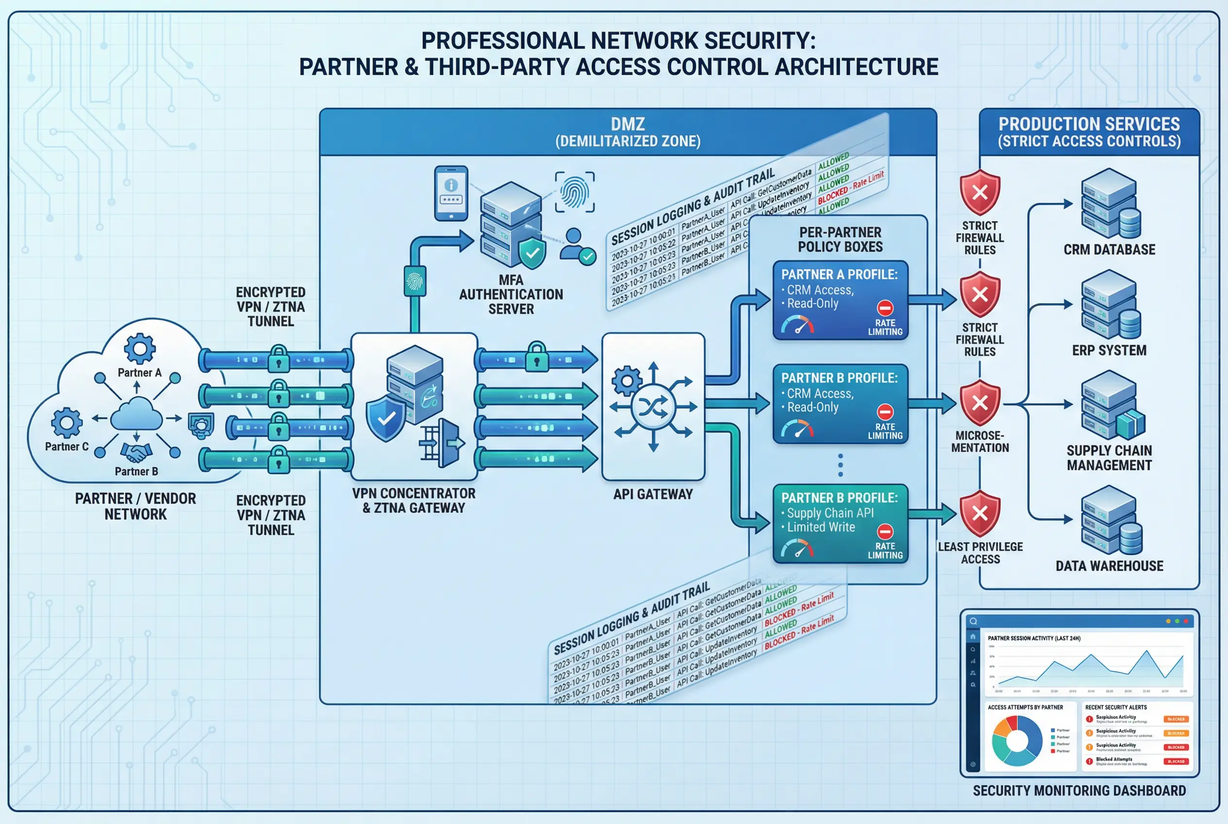
Figure 3.4: Partner Access Control — VPN/ZTNA tunnel from partner network through DMZ MFA gateway to per-partner API policy profiles, with session logging and production service access controls.
Partner and third-party access represents one of the highest-risk access patterns in enterprise networks. Partners often require access to specific APIs or data sets, but their security posture is outside the organization's direct control. The design isolates all partner access through the DMZ, requiring VPN or ZTNA authentication with MFA. An API gateway enforces per-partner rate limits, allowed endpoints, and data access scopes. Session logs are mandatory for all partner access, and partner access profiles are reviewed quarterly. No partner has direct network access to Production or Data zones — all access is mediated through the API gateway.
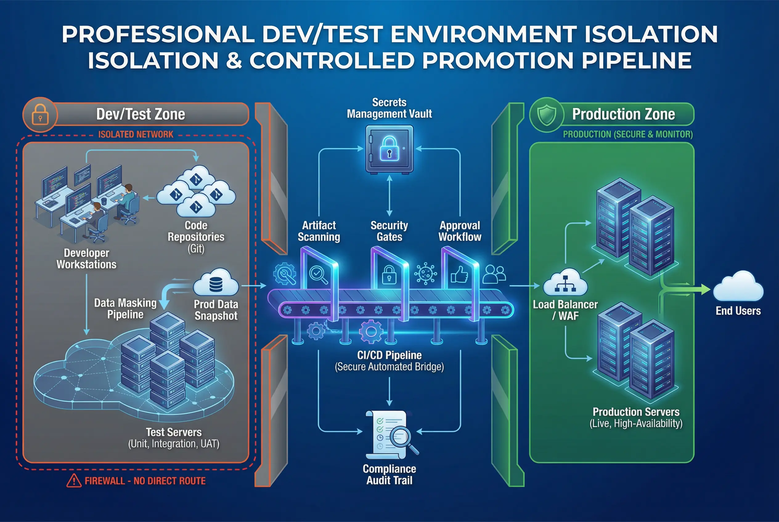
Figure 3.5: Dev/Test Isolation — Isolated Dev/Test zone (orange) with CI/CD pipeline as the only bridge to Production zone (green), showing artifact scanning, security gates, approval workflow, and data masking pipeline.
The Dev/Test isolation scenario addresses the risk of development environments being used as a pivot point into production. Developers require access to realistic test data and the ability to deploy code, but they must not have direct network access to production systems. The design uses a firewall to block all direct routing between Dev/Test and Production, with the CI/CD pipeline as the only authorized promotion path. Test data is derived from production data through a data masking pipeline. Secrets management ensures that production credentials are never stored in development environments. Compliance audit trails capture every promotion event.
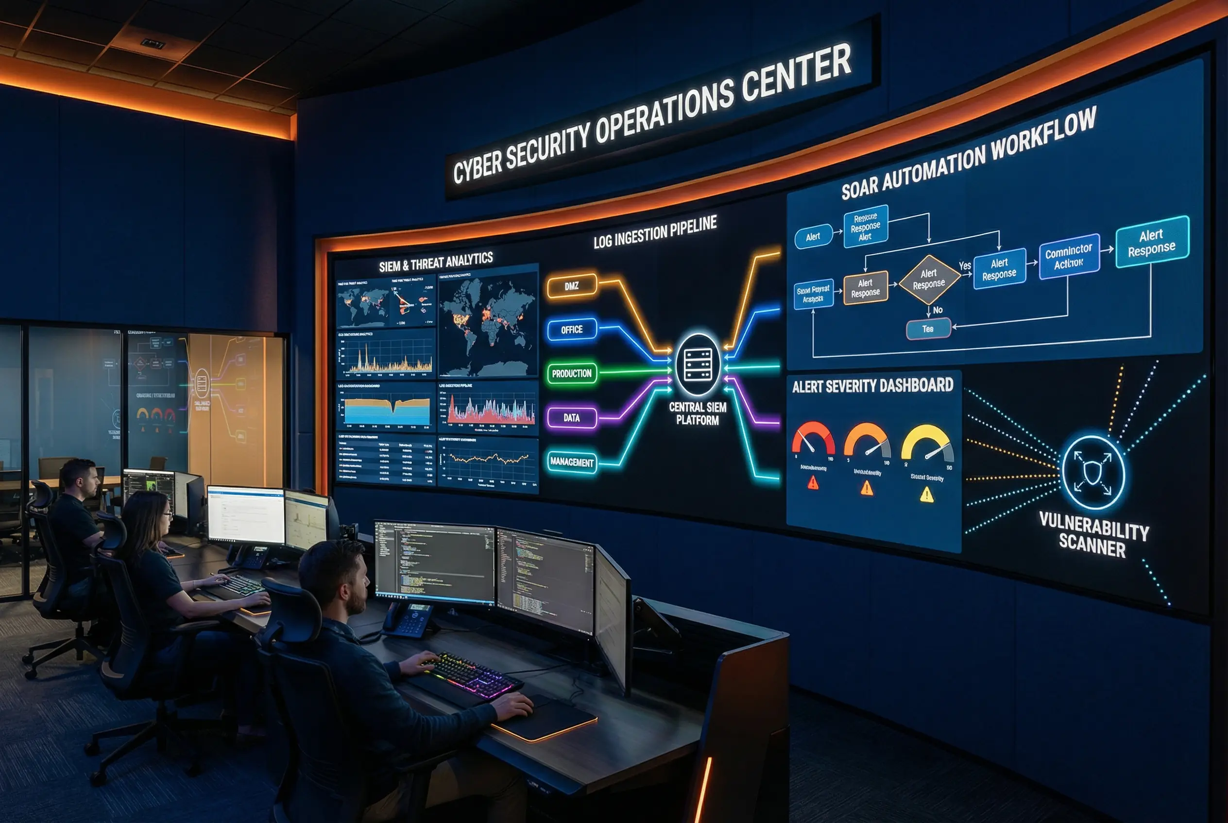
Figure 3.6: SOC Centralization — Security Operations Center with SIEM receiving log streams from all network zones, SOAR automation workflow, alert severity dashboard, and vulnerability scanner with limited active reach.
The SOC centralization scenario addresses the challenge of giving the security team visibility into all zones without granting them administrative access that could be abused or compromised. The SIEM receives log streams from all zones via one-way log forwarding — the SIEM cannot initiate connections back into production zones. The vulnerability scanner has limited active reach, with scan credentials managed by PAM and scan schedules approved by zone owners. SOAR playbooks automate tier-1 response actions such as quarantining a compromised host or blocking a malicious IP, with human approval required for higher-impact actions.
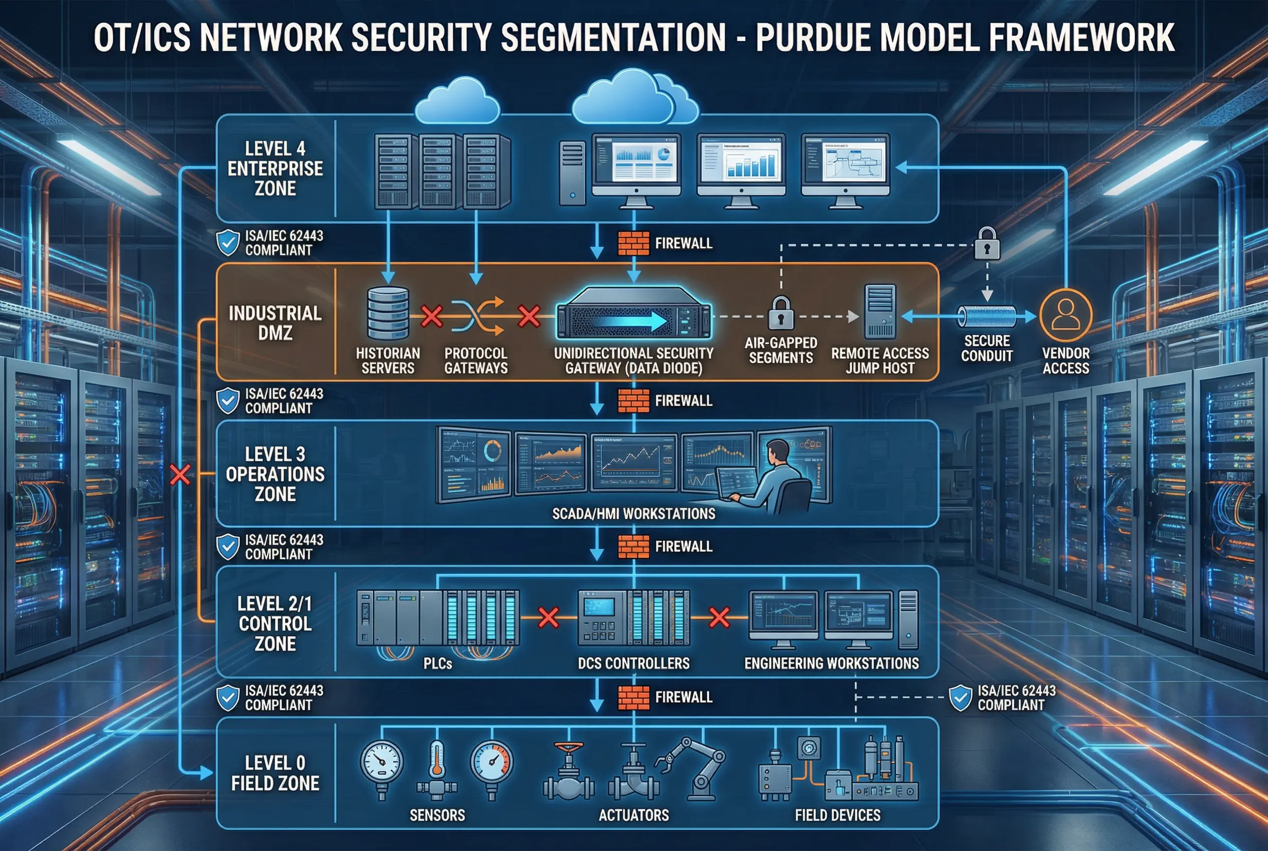
Figure 3.7: OT/ICS Purdue Model — Five-level hierarchy from Enterprise (Level 4) through Industrial DMZ to Operations (Level 3), Control (Level 2/1), and Field (Level 0), with unidirectional security gateways and ISA/IEC 62443 compliance labels.
The OT/ICS scenario requires the most conservative segmentation approach. Industrial control systems often run legacy operating systems that cannot be patched, and a security incident can have physical safety consequences. The design follows the ISA/IEC 62443 Purdue model, with strict conduits between each level and an Industrial DMZ that mediates all data exchange between the enterprise IT network and the OT network. Unidirectional security gateways (data diodes) are used where data must flow from OT to IT without any possibility of reverse communication. Remote vendor access is restricted to a dedicated jump host in the Industrial DMZ with session recording and time-limited access tokens.
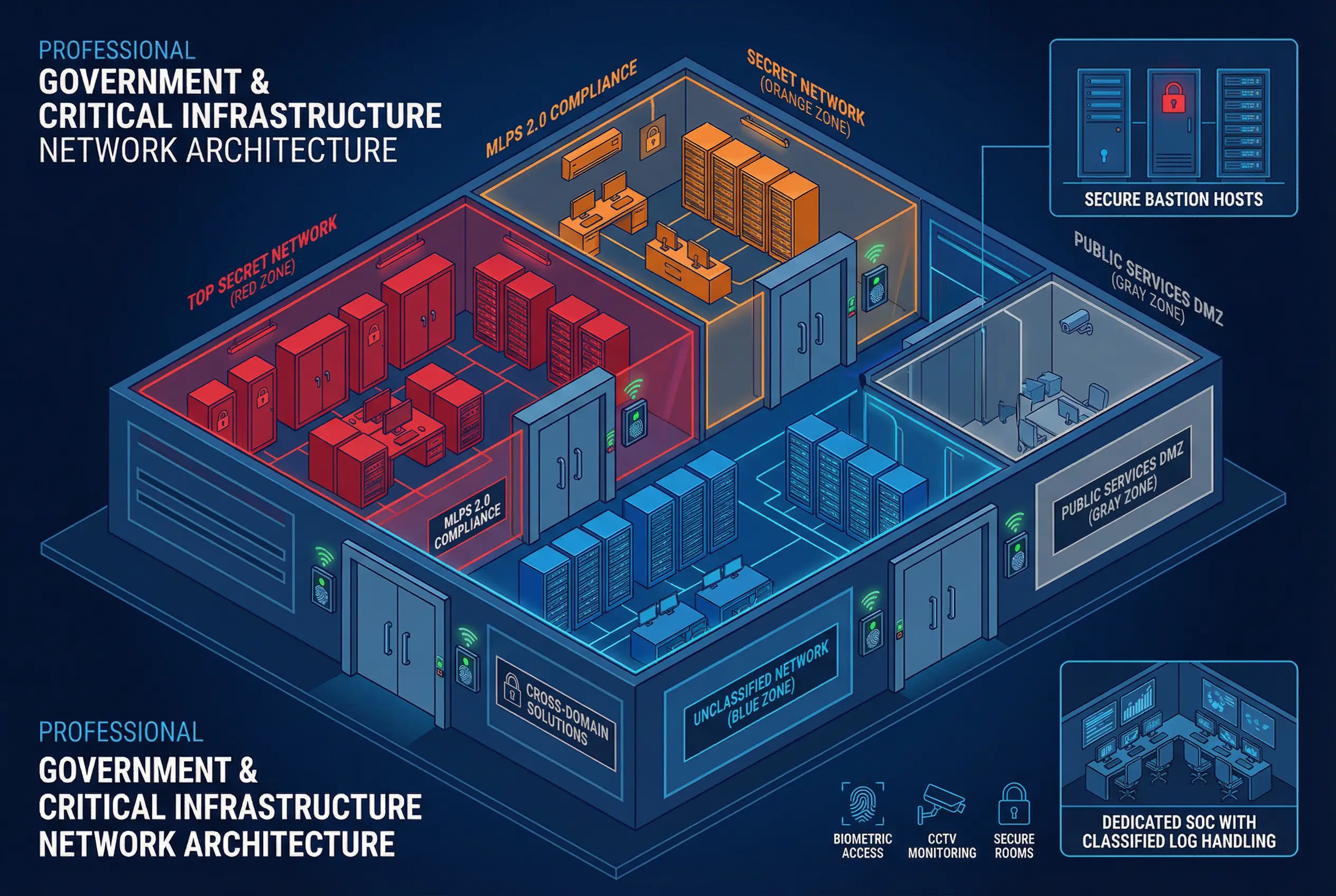
Figure 3.8: Government & Critical Infrastructure — Isometric building showing physically separated classification zones (Top Secret/red, Secret/orange, Unclassified/blue, Public DMZ/gray) with cross-domain solutions, biometric access controls, and dedicated SOC.
Government and critical information infrastructure environments require the highest level of segmentation rigor, often including physical separation between classification levels. The design implements separate network fabrics for each classification level, with cross-domain solutions (CDS) as the only authorized data transfer path between levels. MLPS 2.0 compliance requirements mandate specific controls for each protection level, including dedicated audit systems, physical access controls, and classified log handling procedures. The public services DMZ is completely separated from all classified networks and is treated as an untrusted zone even for internal users.
Scenario Selection Matrix
The following matrix helps engineering teams select the most appropriate scenario or combination of scenarios based on their environment characteristics. Multiple scenarios can apply simultaneously — for example, a government data center would combine elements of Scenarios B, G, and H.
| Environment Type | Primary Scenario | Secondary Scenario | Complexity | Key Differentiator |
|---|---|---|---|---|
| Enterprise campus with office users | A | D (if partners) | Medium | 802.1X NAC + VLAN enforcement |
| On-premises data center | B | F (SOC) | High | East-west micro-segmentation |
| Multi-cloud or hybrid cloud | C | F (SOC) | High | Policy-as-code + ZTNA |
| SaaS/API platform with partners | D | B or C | Medium | Per-partner API policy |
| Software development organization | E | A or B | Medium | CI/CD as the only promotion path |
| Security-focused organization | F | All others | High | SIEM + SOAR centralization |
| Manufacturing / industrial facility | G | A (IT side) | Very High | Purdue model + data diodes |
| Government / critical infrastructure | H | B + G | Highest | Physical separation + CDS |