Chapter 4: Architecture Design
Typical system topology, physical device wiring, inter-zone access matrix, and HA design patterns for production-grade segmentation deployments.
4.1 Typical System Topology
The typical system topology for a production-grade segmentation deployment organizes security enforcement and operational tooling into eight distinct zones, each with a defined trust level and a set of permitted inter-zone flows. The topology is designed to be modular — organizations can implement a subset of zones initially and expand over time as their security maturity grows. The minimum viable deployment includes an edge NGFW, a DMZ zone, an Office zone, a Production zone, and a Management zone with a bastion host.
The topology diagram below illustrates the full reference architecture, including all eight zones, the enforcement points at each boundary, and the labeled traffic flows between zones. Every arrow in the diagram represents a documented, controlled conduit — there are no implicit trust relationships between zones.
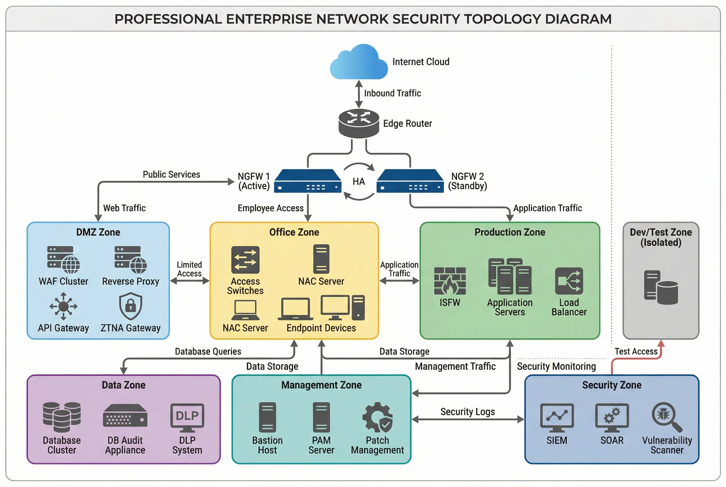
Figure 4.1: Typical System Topology — Complete eight-zone reference architecture showing edge NGFW HA pair, DMZ (WAF/API/ZTNA), Office (NAC/endpoints), Production (ISFW/apps/LB), Data (DB/DLP), Management (bastion/PAM), Security (SIEM/SOAR), and isolated Dev/Test zone with labeled inter-zone traffic flows.
Zone Trust Hierarchy
The trust hierarchy defines the default posture between zones. A higher trust level does not mean unrestricted access — it means that the zone contains more sensitive assets and therefore receives more protective controls. The table below summarizes the trust level, default inter-zone stance, and the primary enforcement mechanism for each zone.
| Zone | Trust Level | Default Stance to Other Zones | Primary Enforcement | Minimum HA Requirement |
|---|---|---|---|---|
| Internet / External | 0 (Untrusted) | Deny all inbound; allow only published services | Edge NGFW | Dual ISP + HA NGFW pair |
| DMZ | 30 (Semi-trusted) | Deny to Office/Prod/Data; allow to Internet via proxy | NGFW + WAF | HA WAF cluster + HA NGFW |
| Office / User | 50 (Low-Medium) | Deny to Production direct; allow via published paths | ISFW + NAC | Redundant access switches |
| Production / Service | 70 (Medium) | Allow from Office via published paths; deny to Data direct | ISFW + host FW | HA ISFW pair |
| Data / Core Data | 85 (High) | Allow from Production via service accounts only | ISFW + DB audit | HA ISFW + DB cluster |
| Management / O&M | 90 (High-Privileged) | Allow admin to all zones via bastion only | Bastion + PAM + MFA | HA bastion pair |
| Security / SOC | 90 (High-Visibility) | Receive logs from all zones; no admin to production | SIEM + SOAR | HA SIEM cluster |
| Dev / Test | 40 (Low-Medium) | No direct routing to Production; CI/CD only | FW deny routing | Best-effort (non-production) |
4.2 Physical Device Wiring and Connection Design
The physical wiring design translates the logical topology into a concrete rack layout with specific cable types, port assignments, and redundancy paths. Correct physical wiring is essential for HA failover to work as designed — a single cable failure should never take down a security boundary. The wiring design must be documented and verified during acceptance testing, with as-built diagrams updated after any changes.
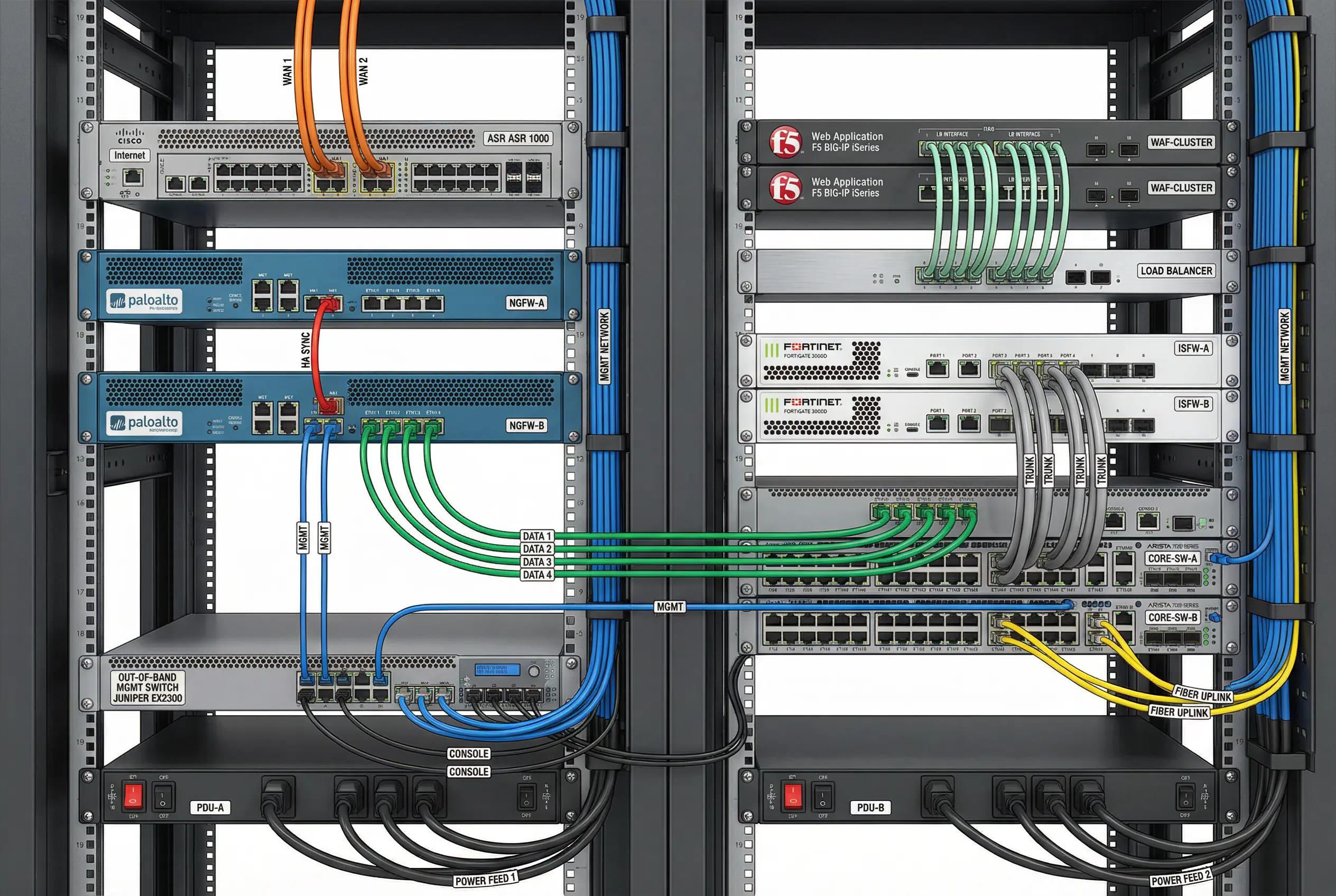
Figure 4.2: Physical Device Wiring — Rack-level view showing dual NGFW appliances with HA sync cable (red), data ports (green), management network (blue), WAF cluster with load balancer cables, ISFW HA pair with trunk cables, core switches with fiber uplinks (yellow), and out-of-band management switch with console cables.
Cable Color Coding Standard
| Cable Color | Network Function | Typical Speed | Notes |
|---|---|---|---|
| Orange | WAN / Internet uplinks | 1–10Gbps | Dual ISP links; never share a physical path |
| Red | HA synchronization links | 1–10Gbps | Direct cable between HA peers; no switch in path |
| Blue | Management / OOB network | 1Gbps | Separate physical network; never shared with data |
| Green | Data plane / zone interfaces | 1–25Gbps | Zone-specific; labeled with zone name |
| Yellow | Fiber uplinks (inter-switch) | 10–100Gbps | Redundant pairs; different physical paths |
| Gray | Console cables | Serial | OOB access for recovery; label with device name |
4.3 Inter-Zone Access Matrix
The inter-zone access matrix is the central policy document for the segmentation design. It defines, for each source-destination zone pair, whether traffic is permitted or denied by default, and what the allowed services are for permitted flows. The matrix must be reviewed and approved by the security team and zone owners before implementation, and it must be updated whenever a new flow is required. The matrix below represents the default baseline — specific deployments will add rows for application-specific flows.
| Source Zone → | Internet | DMZ | Office | Production | Data | Management | Security | Dev/Test |
|---|---|---|---|---|---|---|---|---|
| Internet | — | Published services only (80/443) | DENY | DENY | DENY | DENY | DENY | DENY |
| DMZ | Proxy outbound only | — | DENY | App ports only (documented) | DENY | DENY | Log push only | DENY |
| Office | Via proxy/NGFW | DENY direct; via proxy | — | Published app ports only | DENY | DENY direct; via bastion | Log push only | DENY |
| Production | DENY direct; via proxy | DENY | DENY | — | DB ports, svc accounts only | DENY direct; via bastion | Log push only | DENY |
| Data | DENY | DENY | DENY | DB response only | — | DENY direct; via bastion | Log push only | DENY |
| Management | DENY | Admin via bastion | DENY | Admin via bastion | Admin via bastion | — | Admin via bastion | Admin via bastion |
| Security | Threat intel feeds | DENY active; receive logs | DENY active; receive logs | DENY active; receive logs | DENY active; receive logs | DENY active; receive logs | — | DENY active; receive logs |
| Dev/Test | Via proxy | DENY | DENY | DENY direct; CI/CD only | DENY | DENY direct; via bastion | Log push only | — |
4.4 High Availability Design Patterns
Every boundary enforcement point must have a defined HA design. The choice of HA pattern depends on the recovery time objective (RTO), the traffic volume, and the operational complexity the team can sustain. The three primary HA patterns used in segmentation deployments are described below, along with their trade-offs and recommended use cases.
| HA Pattern | Description | RTO | Traffic Handling | Recommended Use Case | Key Risk |
|---|---|---|---|---|---|
| Active-Passive (A/P) | One active device handles all traffic; passive device takes over on failure | <30s | Active handles 100%; passive is idle | Edge NGFW, ISFW for most deployments | Passive capacity wasted; failover causes brief interruption |
| Active-Active (A/A) | Both devices handle traffic simultaneously; load balanced | <5s | Each handles 50–60%; both active | High-throughput WAF, ISFW in data centers | State synchronization complexity; asymmetric routing issues |
| Cluster (3+ nodes) | Multiple nodes share traffic; any node can fail without service impact | <1s | Distributed across all nodes | SIEM, bastion, large-scale WAF | Higher cost; complex state management; split-brain risk |