Chapter 11: Installation & Debugging
Step-by-step installation procedures, pre-installation requirements, physical installation standards, initial configuration sequence, and systematic debugging methodology for network security segmentation deployments.
A disciplined installation process is the foundation of a reliable segmentation deployment. Errors introduced during installation — incorrect cable routing, misconfigured interfaces, wrong VLAN assignments — are significantly harder to diagnose and remediate after the system is in production. This chapter provides a structured installation methodology that minimizes the risk of installation errors and provides a systematic approach to debugging when issues are encountered.
11.1 Installation Requirements
The following installation requirements must be verified and documented before any equipment is racked. A pre-installation site survey should be conducted at least one week before the planned installation date to identify any gaps. The site survey report must be reviewed and signed off by the project manager and the data center facilities manager before installation begins.
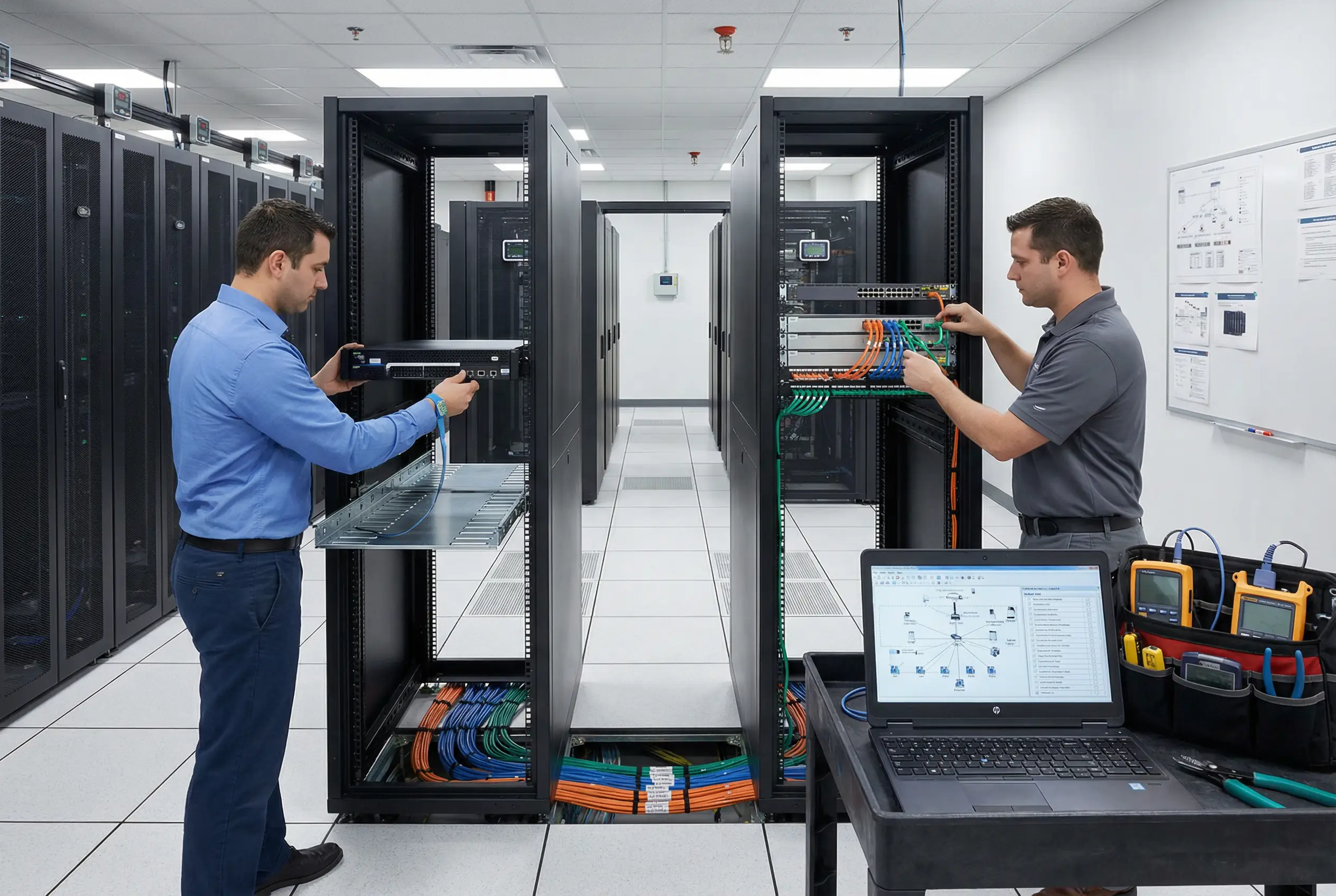
Figure 11.1: Installation Requirements in Practice — Professional engineers installing NGFW appliances and color-coded patch cables in a modern data center. Left engineer uses ESD strap while mounting appliance; right engineer routes color-coded cables (orange WAN, blue management, green data) through cable management trays. Laptop on cart displays network diagram and installation checklist; tool bag contains cable tester and fiber power meter.
Table 11-1: Pre-Installation Site Requirements
| Requirement Category | Specific Requirement | Minimum Standard | Verification Method | Responsible Party |
|---|---|---|---|---|
| Rack Space | Available rack units for all appliances + 20% spare | Minimum 10U per security rack | Physical rack audit | DC Facilities |
| Power | Redundant A+B power feeds to each rack | 16A per feed, 2 feeds per rack | Electrician measurement | DC Facilities |
| Cooling | Adequate cooling for added heat load | ≤25°C inlet temperature | Temperature measurement | DC Facilities |
| Network Connectivity | Uplink ports available on distribution switches | 10GbE or 25GbE uplinks | Switch port audit | Network Team |
| Out-of-Band Management | OOB network ports available for all appliances | 1GbE OOB per appliance | OOB switch audit | Network Team |
| Physical Security | Rack locking and access control | Keyed rack locks; access log | Physical inspection | DC Facilities |
| Cable Plant | Patch cables and fiber available per cable plan | Per Chapter 4 cable plan | Cable inventory check | Network Team |
| IP Addressing | IP addresses allocated for all interfaces | Per IPAM allocation | IPAM review | Network Team |
| DNS Entries | DNS A records created for all management IPs | Forward + reverse DNS | DNS lookup test | Network Team |
| NTP Reachability | NTP servers reachable from management network | 2+ NTP sources | NTP test from OOB | Network Team |
| SIEM Connectivity | Syslog/API path from appliances to SIEM | UDP/TCP 514 or API | Port connectivity test | Security Team |
| Backup Storage | Backup storage accessible from management network | SFTP or API accessible | Connectivity test | Network Team |
11.2 Physical Installation Sequence
The physical installation must follow the sequence below to minimize the risk of errors and ensure that each step can be verified before proceeding to the next. Do not skip steps or perform steps out of order. Each step must be signed off in the installation checklist before proceeding.
- Rack preparation: Install cable management trays and blanking panels. Verify power feeds are de-energized before working in the rack. Install PDUs on both A and B sides.
- Appliance physical installation: Mount appliances in the rack using vendor-supplied rack ears. Verify appliance is seated correctly and screws are tightened. Do not power on yet.
- Power cabling: Connect power cables from appliance to PDU. Connect A-side power to A-side PDU and B-side power to B-side PDU. Verify power cable routing through cable management.
- Console cable connection: Connect console cables to all appliances before powering on. Verify console access from the OOB management laptop before proceeding.
- Initial power-on and POST verification: Power on appliances one at a time. Verify POST completes without errors. Record serial numbers and firmware versions.
- OOB management cable connection: Connect management interface cables (blue) to OOB management switch. Verify management IP is reachable from OOB network.
- Data plane cable connection: Connect data plane cables in the following order: WAN/Internet (orange), HA sync (red), zone interfaces (green), monitoring (yellow). Label each cable at both ends immediately after connection.
- Fiber optic connections: Clean fiber connectors before insertion. Connect fiber cables and verify link light on both ends. Measure fiber power levels and record in cable plant documentation.
- Cable dressing: Route and bundle cables through cable management trays. Use velcro ties — do not use zip ties (they cannot be removed without cutting). Verify no cables are under tension or sharply bent.
- Physical inspection and documentation: Photograph the completed rack from front and rear. Update the as-built cable plant documentation. Sign off the physical installation checklist.
11.3 Initial Configuration Sequence
After physical installation is complete and verified, the initial software configuration must follow the sequence below. Configuration should be performed via the console connection initially, before network connectivity is established, to avoid configuration errors that could lock out network access. Each configuration step should be saved and backed up before proceeding to the next.
| Step | Configuration Task | Method | Verification | Rollback Plan |
|---|---|---|---|---|
| 1 | Set hostname and management IP | Console CLI | Ping management IP from OOB | Console reset |
| 2 | Change default admin password; disable default accounts | Console CLI | Login with new credentials | Factory reset (last resort) |
| 3 | Configure NTP servers | CLI or GUI | Verify time sync; check drift | Reconfigure NTP |
| 4 | Configure DNS servers | CLI or GUI | Resolve internal hostname | Reconfigure DNS |
| 5 | Configure LDAP/RADIUS integration | GUI | Test LDAP bind; test admin login | Revert to local auth |
| 6 | Import certificates (TLS inspection CA, admin cert) | GUI | Verify cert chain; check expiry | Remove cert; use self-signed |
| 7 | Configure interface IP addresses and zones | GUI | Ping each interface from adjacent device | Reconfigure interface |
| 8 | Configure HA (if applicable) | GUI | HA status shows synchronized | Disable HA; operate standalone |
| 9 | Import baseline firewall policy | GUI / API | Verify policy count; test key flows | Revert to previous policy |
| 10 | Configure syslog/log forwarding to SIEM | GUI | Verify logs appear in SIEM | Reconfigure syslog |
| 11 | Configure SNMP monitoring | GUI / CLI | Verify device appears in NMS | Reconfigure SNMP |
| 12 | Take configuration backup | Automated backup system | Verify backup file in storage | Manual backup via CLI |
11.4 Systematic Debugging Methodology
When connectivity issues are encountered during or after installation, a systematic OSI-layer-by-layer approach is the most efficient debugging methodology. Starting from Layer 1 and working up ensures that lower-layer issues are not masked by higher-layer symptoms. The following debugging sequence should be followed for any connectivity issue.
| OSI Layer | Common Issues | Diagnostic Commands / Tools | Resolution |
|---|---|---|---|
| Layer 1 — Physical | No link light; wrong cable; fiber dirty | Check link LED; cable tester; fiber power meter | Replace cable; clean fiber; check SFP |
| Layer 2 — Data Link | Wrong VLAN; STP blocking; duplex mismatch | show interfaces; show vlan; show spanning-tree | Correct VLAN; fix STP; set duplex/speed |
| Layer 3 — Network | Wrong IP; missing route; wrong gateway | ping; traceroute; show route; show arp | Correct IP; add route; fix gateway |
| Layer 4 — Transport | Port blocked by firewall; NAT issue | telnet/nc port test; firewall log review | Add firewall rule; fix NAT config |
| Layer 7 — Application | TLS cert error; auth failure; DNS failure | curl -v; openssl s_client; nslookup | Fix cert; fix auth; fix DNS record |
| Firewall Policy | Traffic matching wrong rule; implicit deny | Firewall traffic log; policy trace/simulator | Reorder rules; add explicit permit |
| NAC / 802.1X | Device not authenticated; wrong VLAN assigned | NAC event log; RADIUS log; switch port status | Fix certificate; fix RADIUS policy |
11.5 Common Installation Errors and Prevention
| Error | Consequence | Prevention | Detection |
|---|---|---|---|
| Cable connected to wrong port | Traffic routed to wrong zone; security bypass | Follow cable plan; label before connecting | Connectivity test; traffic capture |
| Wrong VLAN on trunk port | Zone traffic not isolated; cross-zone leakage | Verify VLAN config against design before cutover | VLAN scan; traffic capture |
| HA sync link on wrong interface | HA sync fails; split-brain risk | Verify HA interface assignment in config | HA status check immediately after config |
| Default deny rule missing | Implicit permit allows unauthorized traffic | Include explicit default-deny in policy template | Test with unauthorized traffic; policy review |
| Management interface on data VLAN | Management traffic exposed to user zone | Verify management interface is on OOB VLAN | Attempt management access from user zone |
| NTP not configured | Log timestamps incorrect; Kerberos failures | Include NTP in initial config checklist | Check time drift; compare with reference |